Advanced Lane Finding

Advanced Lane Finding Project
The goals / steps of this project are the following:
- Compute the camera calibration matrix and distortion coefficients given a set of chessboard images.
- Apply a distortion correction to raw images.
- Use color transforms, gradients, etc., to create a thresholded binary image.
- Apply a perspective transform to rectify binary image (“birds-eye view”).
- Detect lane pixels and fit to find the lane boundary.
- Determine the curvature of the lane and vehicle position with respect to center.
- Warp the detected lane boundaries back onto the original image.
- Output visual display of the lane boundaries and numerical estimation of lane curvature and vehicle position.
Camera Calibration
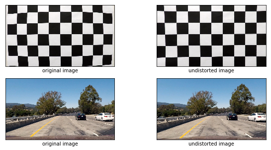
1. Briefly state how you computed the camera matrix and distortion coefficients. Provide an example of a distortion corrected calibration image.
The code for this step is contained in the 13th code cell of the IPython notebook
I start by preparing “object points”, which will be the (x, y, z) coordinates of the chessboard corners in the world. Here I am assuming the chessboard is fixed on the (x, y) plane at z=0, such that the object points are the same for each calibration image. Thus, objp is just a replicated array of coordinates, and objpoints will be appended with a copy of it every time I successfully detect all chessboard corners in a test image. imgpoints will be appended with the (x, y) pixel position of each of the corners in the image plane with each successful chessboard detection.
I then used the output objpoints and imgpoints to compute the camera calibration and distortion coefficients using the cv2.calibrateCamera() function. I applied this distortion correction to the test image using the cv2.undistort() function and obtained this result:
Pipeline (single images)
1. Provide an example of a distortion-corrected image.
To demonstrate this step, I described how I apply the distortion correction to one of the test images in the previous example
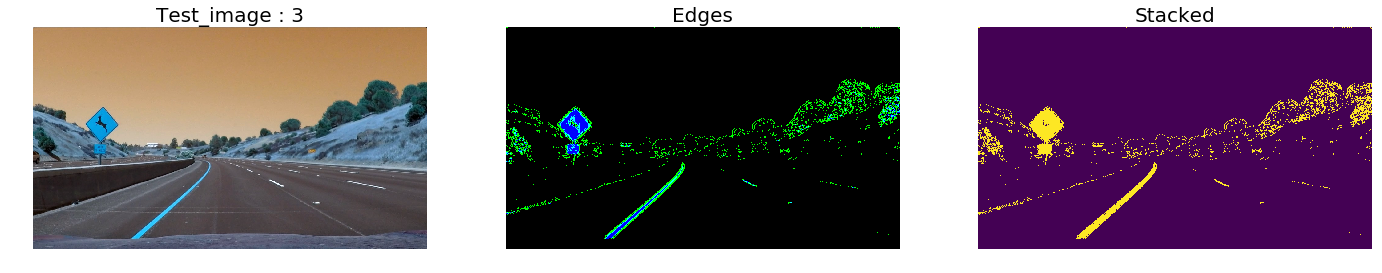
2. Describe how (and identify where in your code) you used color transforms, gradients or other methods to create a thresholded binary image. Provide an example of a binary image result.
I started and experimented with gradient absolute value, then gradient magnitude, gradient direction and aslo extracted an tresholded s channel from HLS colorspace.
I used a combination of color and gradient thresholds to generate a binary image (thresholding steps at cells 11 through 32). Here’s an example of my output for this step.
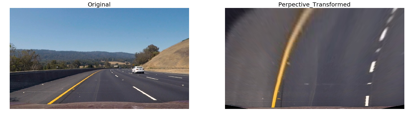
3. Describe how (and identify where in your code) you performed a perspective transform and provide an example of a transformed image.
The code for my perspective transform appears cell 35. The function takes as inputs an image (img), as well as source (src) and destination (dst) points. I chose the hardcode the source and destination points in the following manner:
python
pt1 = [w // 2 - 76, h* 0.625]
pt2 = [w // 2 + 76, h * 0.625]
pt3 = [-100, h]
pt4 = [w + 100, h]

src = np.float32([pt1, pt2, pt3, pt4])

dp1 = [100, 0]
dp2 = [w - 100, 0]
dp3 = [100, h]
dp4 = [w - 100, h]
dst = np.float32([dp1, dp2, dp3, dp4])
I verified that my perspective transform was working as expected by drawing the src and dst points onto a test image and its warped counterpart to verify that the lines appear parallel in the warped image.
4. Describe how (and identify where in your code) you identified lane-line pixels and fit their positions with a polynomial?
I extracted points belonging to left and left lane, stored them in an array and tried fit my lane lines with a 2nd order polynomial .
5. Describe how (and identify where in your code) you calculated the radius of curvature of the lane and the position of the vehicle with respect to center.
I calulate the radius if curvature using the followiing formulae, please fine the code in cell 87 `

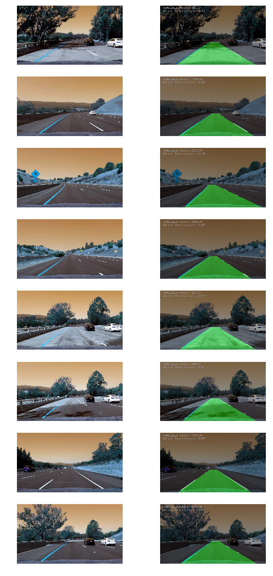
6. Provide an example image of your result plotted back down onto the road such that the lane area is identified clearly.
I implemented this step in cell 164. Here is an example of my result on a test image:
Pipeline (video)
1. Provide a link to your final video output. Your pipeline should perform reasonably well on the entire project video (wobbly lines are ok but no catastrophic failures that would cause the car to drive off the road!).
Here’s a link to my video result
Discussion
1. Briefly discuss any problems / issues you faced in your implementation of this project. Where will your pipeline likely fail? What could you do to make it more robust?
- Thresholding is a cocern when dealing with shadows and different light intensity environement.
- Lane starting window finding was not so robust for lane finding using histograms.